Putting songs in a kid’s toy: an ESP32 MP3 player and a custom NS4168 amp board
October 6, 2026
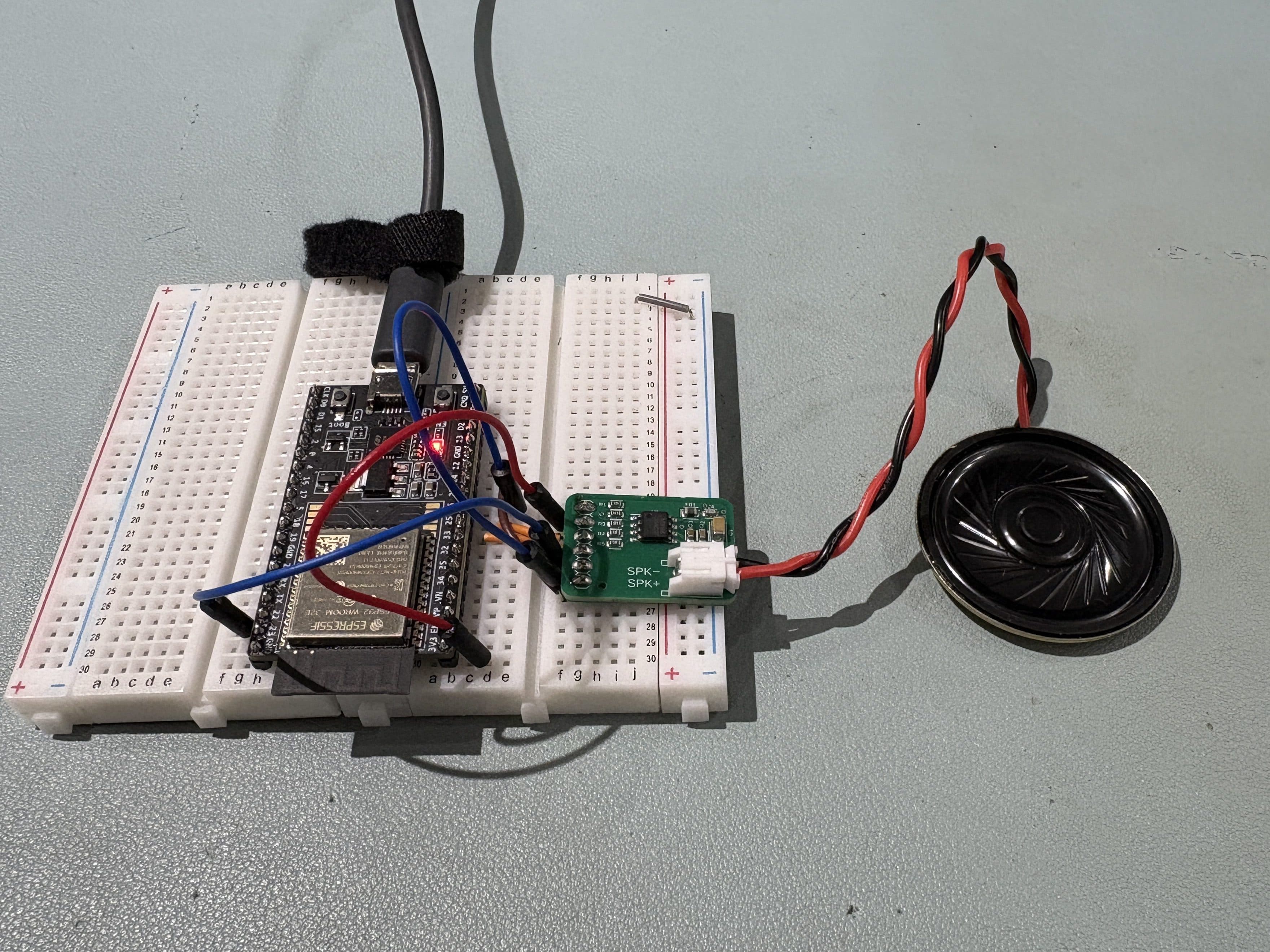
Key points
- Three MP3 files stored in the ESP32’s internal flash (LittleFS) play through an NS4168 I2S amplifier.
- The silence I fought came from a wrong pin (DATA instead of SDATA). I also blamed the sample rate at first; a retest showed it had nothing to do with it.
- I replaced the amp module with my own board, built by JLCPCB, and confirmed that it runs from 3.3 V.
About this article
This is the English version of an article I first wrote in Japanese. The Japanese original is here.
Introduction
I wanted to put a few songs into a toy for my kid, so I built a player that stores MP3 files in the ESP32’s internal flash and plays them through an I2S amplifier.
The finished setup is simple, but I hit silence and noise several times before any music came out. This is a record of what I tried, in the order I tried it.
| What I did | Result |
|---|---|
| Chose where to store the songs | Internal flash (LittleFS) |
| Played them on a breadboard | Worked with an I2S amp module |
| Built an amp board | Made by JLCPCB; plays from a 3.3 V supply |
The finished setup

The ESP32 decodes MP3 files from its internal flash and sends the audio to the NS4168 over three I2S lines.
Parts and software
| Item | Details |
|---|---|
| MCU | ESP32 DevKit (ESP32-WROOM-32, 4 MB flash) |
| Amplifier | An I2S amp module with an NS4168 (it also carries an LMD2718 MEMS microphone). Later replaced by my own board |
| Speaker | 8 Ω |
| Tools | Arduino IDE 2.3.4, ESP32 core 3.3.10 |
| Library | ESP8266Audio 2.4.1 (despite the name, it runs on the ESP32) |
| Audio | Free tracks, converted to MP3, 48 kbps, 44.1 kHz, mono |
| Storage | LittleFS on the internal flash (about 2.9 MB) |
Wiring (with the module)
| ESP32 | Module | Role |
|---|---|---|
| GPIO26 | BCLK | Bit clock |
| GPIO25 | LRCLK | Left/right clock |
| GPIO22 | SDATA | Audio data |
| 5V (VIN) | 5V | Power |
| GND | GND | Ground |

After this, I replaced the amp module with my own board. The same sketch runs on it from a 3.3 V supply.
Where I bought the module: AliExpress
Choosing where to store the songs
I looked at three options.
| Option | Extra parts | Result in this project |
|---|---|---|
| Voice IC (WT588F02B-8S) | Voice IC | Could not find stock, so not tried |
| microSD card | A player or card module, plus the card | Played |
| Internal flash (chosen) | None | Played |
Voice IC: no stock
Voice ICs such as the WT588F are the usual way to put sound in a toy. My first choice was the WT588F02B-8S.
I planned to have JLCPCB assemble the board, so I checked stock. This is what I found in August 2026.
- JLCPCB has a part page for it (C2917616)
- The LCSC product page returns 404, and the part does not show up in stock search
I could not find stock for other voice ICs either, so I switched to an ESP32 with an I2S amplifier (NS4168, C910588), which is well stocked.
Caution
Stock changes. Check it yourself before you order.
microSD card: it works, but it adds parts
I tried two microSD routes. One was a DFPlayer Mini, an MP3 player module with its own card slot that the ESP32 controls over UART. The other was a plain microSD module on SPI, with the ESP32 reading and decoding the files. Playback from the SPI card module worked.
| Item | DFPlayer Mini | SPI microSD module | Internal flash |
|---|---|---|---|
| Extra parts | DFPlayer Mini, microSD card, resistor | Card module, microSD card | None |
| Extra wiring | UART, 2 signal lines (TX, RX), plus power | SPI, 4 signal lines (SCK, MOSI, MISO, CS), plus power | None |
| Changing songs | Copy files to the card | Copy files to the card | Flash from a PC |
| Capacity | Large | Large | About 2.9 MB in this build |
Internal flash needs no extra parts and no extra wiring. That is what I went with.

Reference (in Japanese): Controlling a DFPlayer over UART
Internal flash: three songs fit in 4 MB

I split the 4 MB flash into 1 MB for the sketch and about 2.9 MB for LittleFS. Three songs of roughly two minutes each fit at 48 kbps.
| File | Size |
|---|---|
| 00001.mp3 | 681,866 bytes |
| 00002.mp3 | 763,525 bytes |
| 00003.mp3 | 742,992 bytes |
| Total | 2,188,383 bytes (71% of the partition) |
Estimating MP3 size
Size (bytes) = bit rate (bps) × seconds ÷ 8
A 120-second song at 48 kbps is 48,000 × 120 ÷ 8 = 720,000 bytes. The sample rate does not affect the size.
The three songs are free tracks that are distributed at no charge. They are not my own recordings and not commercial releases.
Getting the songs onto the ESP32
| Step | What to do | Tool |
|---|---|---|
| 1 | Split the flash into a sketch area and a song area | partitions.csv, Arduino IDE |
| 2 | Convert the MP3s to 48 kbps, 44.1 kHz, mono | ffmpeg |
| 3 | Pack the MP3s into a LittleFS image | Python (littlefs-python) |
| 4 | Flash the image to the ESP32 | esptool |
1. Split the flash
Put partitions.csv in the same folder as the sketch, then choose Custom under Tools → Partition Scheme in the Arduino IDE.
File partitions.csv
# Name, Type, SubType, Offset, Size, Flagsnvs, data, nvs, 0x9000, 0x5000,otadata, data, ota, 0xe000, 0x2000,app0, app, ota_0, 0x10000, 0x100000,spiffs, data, spiffs, 0x110000, 0x2F0000,
Each line is one partition. From the top:
| Name | Offset | Size | Used for |
|---|---|---|---|
| nvs | 0x9000 | 20 KB | Settings storage |
| otadata | 0xe000 | 8 KB | Which app to boot |
| app0 | 0x10000 | 1 MB | The sketch |
| spiffs | 0x110000 | about 2.9 MB | Songs (used as LittleFS) |
Note
The partition can keep the name spiffs and still be used as LittleFS. The offset 0x110000 is needed again when you flash the songs.
2. Convert the MP3s
Command Convert an MP3
ffmpeg -i input.mp3 -ac 1 -ar 44100 -b:a 48k -map_metadata -1 00001.mp3
input.mp3 is the original file and 00001.mp3 is the converted one.
| Option | Meaning |
|---|---|
-ac 1 | Mono |
-ar 44100 | 44.1 kHz sample rate (16 kHz and 22.05 kHz also play; see pitfall 4 below) |
-b:a 48k | 48 kbps bit rate |
-map_metadata -1 | Strip tags |
3. Build the LittleFS image
Normally the arduino-littlefs-upload plugin for Arduino IDE 2.x uploads the whole data folder for you.
On my machine (Arduino IDE 2.3.4) the command never appeared in the command palette, so I built the image with littlefs-python instead.
Lay out the folder like this.
Folder layout
work/├─ make_littlefs.py <- the script below├─ data/│ ├─ 00001.mp3│ ├─ 00002.mp3│ └─ 00003.mp3└─ littlefs.bin <- created when you run it
Python make_littlefs.py
from littlefs import LittleFSimport os, globSIZE, BLOCK, PROG = 0x2F0000, 4096, 256fs = LittleFS(block_size=BLOCK, block_count=SIZE // BLOCK, read_size=PROG, prog_size=PROG, disk_version=0x00020000)for p in sorted(glob.glob("data/*.mp3")): with fs.open("/" + os.path.basename(p), "wb") as f: f.write(open(p, "rb").read())open("littlefs.bin", "wb").write(bytes(fs.context.buffer))
| Setting | Value | Meaning |
|---|---|---|
SIZE | 0x2F0000 | Size of the song partition. Must match partitions.csv |
BLOCK | 4096 | Flash block size |
PROG | 256 | Read/program unit |
disk_version | 0x00020000 | LittleFS on-disk version 2.0 |
Run these two lines. The first installs the library and is needed only once.
Command Build the image
py -m pip install littlefs-pythonpy make_littlefs.py
An image built with these settings mounted correctly with LittleFS on ESP32 core 3.3.10.
4. Flash it with esptool
Command Flash the song image
py -m esptool --chip esp32 --port COM5 --baud 921600 write-flash 0x110000 littlefs.bin
| Part | Meaning |
|---|---|
--port COM5 | The port the ESP32 is on. Change it to yours |
--baud 921600 | Flashing speed |
write-flash | The write command. esptool v5 renamed it from write_flash |
0x110000 | Where to write. Must match partitions.csv |
littlefs.bin | The image from step 3 |
The commands above are for Windows, where py is the Python launcher. On macOS or Linux, use python3 instead of py, and a port name such as /dev/ttyUSB0.
Caution
If the serial monitor is open, esptool cannot open the port and the write fails. Close it first.
Note
Songs and sketch are flashed separately. The upload button in the Arduino IDE writes only the sketch (at 0x10000).
The sketch
The sketch has five parts. Paste parts 1 to 5 one after another and you have the whole sketch.
For this English version I translated the comments and the serial messages. The code is otherwise the same as in the Japanese article.
| Part | What it does |
|---|---|
| 1. Settings | Pin numbers, the playlist, and the volume |
| 2. Start and stop playback | Opens a file and connects it to the MP3 decoder |
| 3. File list | Prints the files stored in LittleFS |
4. setup() | Runs once at boot. Sets up I2S and starts the first song |
5. loop() | Runs repeatedly. Keeps playback going and handles input |
Part 1: Settings
Arduino Part 1: Settings
#include <Arduino.h>#include <LittleFS.h>#include <AudioFileSourceLittleFS.h>#include <AudioFileSourceBuffer.h>#include <AudioFileSourceID3.h>#include <esp_partition.h>#include <AudioGeneratorMP3.h>#include <AudioOutputI2S.h>constexpr int PIN_I2S_BCLK = 26;constexpr int PIN_I2S_LRC = 25;constexpr int PIN_I2S_DOUT = 22; // to SDATA on the ampconstexpr int PIN_NEXT_SW = 0; // next-track button (-1 to disable)AudioGeneratorMP3 *mp3 = nullptr;AudioFileSourceLittleFS *file = nullptr;AudioFileSourceBuffer *buff = nullptr;AudioFileSourceID3 *id3 = nullptr;AudioOutputI2S *out = nullptr;const char *playlist[] = { "/00001.mp3", "/00002.mp3", "/00003.mp3" };constexpr size_t PLAYLIST_LEN = sizeof(playlist) / sizeof(playlist[0]);size_t currentTrack = 0;float gain = 0.3f;
These are the four things to change for your own setup.
| Change this | What it is |
|---|---|
PIN_I2S_BCLK / PIN_I2S_LRC / PIN_I2S_DOUT | The GPIOs for the three I2S lines |
PIN_NEXT_SW | The GPIO for the next-track button. Use -1 if you have none |
playlist | The files to play. Must match the names stored in LittleFS |
gain | Volume, 0.0 to 2.0 (starts at 0.3) |
Part 2: Start and stop playback
Arduino Part 2: Start and stop playback
void stopPlayback() { if (mp3 && mp3->isRunning()) mp3->stop(); delete id3; id3 = nullptr; delete buff; buff = nullptr; delete file; file = nullptr;}bool startTrack(size_t index) { stopPlayback(); if (!LittleFS.exists(playlist[index])) { Serial.printf("File not found: %s\n", playlist[index]); return false; } file = new AudioFileSourceLittleFS(playlist[index]); buff = new AudioFileSourceBuffer(file, 8192); id3 = new AudioFileSourceID3(buff); if (!mp3) mp3 = new AudioGeneratorMP3(); out->SetGain(gain); bool ok = mp3->begin(id3, out); Serial.printf("Playing: %s (%s)\n", playlist[index], ok ? "OK" : "FAILED"); return ok;}
The audio data flows in this order.
File → buffer → tag handling → MP3 decoder → I2S output
| Class | Role |
|---|---|
AudioFileSourceLittleFS | Reads a file from LittleFS |
AudioFileSourceBuffer | Buffers 8192 bytes of what was read |
AudioFileSourceID3 | Handles the tag data at the start of the MP3 |
AudioGeneratorMP3 | Decodes MP3 |
AudioOutputI2S | Sends the samples out over I2S |
Part 3: File list
Arduino Part 3: File list
void listFiles() { Serial.println("--- Files in LittleFS ---"); File root = LittleFS.open("/"); for (File f = root.openNextFile(); f; f = root.openNextFile()) { Serial.printf(" %-16s %8u bytes\n", f.name(), (unsigned)f.size()); } Serial.printf("Used: %u / %u bytes\n", (unsigned)LittleFS.usedBytes(), (unsigned)LittleFS.totalBytes());}
This prints the stored files at boot, so you can see whether the songs are really there.
Part 4: setup()
Arduino Part 4: setup()
void setup() { Serial.begin(115200); delay(300); if (PIN_NEXT_SW >= 0) pinMode(PIN_NEXT_SW, INPUT_PULLUP); // Print where the song partition actually is const esp_partition_t *p = esp_partition_find_first( ESP_PARTITION_TYPE_DATA, ESP_PARTITION_SUBTYPE_DATA_SPIFFS, NULL); if (p) { Serial.printf("Song partition: start=0x%06X size=%u bytes\n", (unsigned)p->address, (unsigned)p->size); } else { Serial.println("Song partition not found. Set Partition Scheme to Custom."); } out = new AudioOutputI2S(); out->SetBuffers(12, 1024); out->SetPinout(PIN_I2S_BCLK, PIN_I2S_LRC, PIN_I2S_DOUT); out->SetRate(44100); out->SetGain(gain); if (!LittleFS.begin(false)) { Serial.println("LittleFS mount failed"); return; } listFiles(); startTrack(currentTrack); Serial.println("n=next / p=previous / s=stop / +,-=volume");}
| Order | Action |
|---|---|
| 1 | Start the serial port at 115200 bps |
| 2 | Set the next-track button pin as an input |
| 3 | Print where the song partition is and how big it is |
| 4 | Create the I2S output and set its pins and 44.1 kHz |
| 5 | Mount LittleFS and print the file list |
| 6 | Start the first song |
Part 5: loop()
Arduino Part 5: loop()
void loop() { if (mp3 && mp3->isRunning()) { if (!mp3->loop()) { mp3->stop(); currentTrack = (currentTrack + 1) % PLAYLIST_LEN; startTrack(currentTrack); } } if (Serial.available()) { char c = Serial.read(); if (c == 'n') { currentTrack = (currentTrack + 1) % PLAYLIST_LEN; startTrack(currentTrack); } else if (c == 'p') { currentTrack = (currentTrack + PLAYLIST_LEN - 1) % PLAYLIST_LEN; startTrack(currentTrack); } else if (c == 's') { stopPlayback(); } else if (c == '+' || c == '-') { gain += (c == '+') ? 0.1f : -0.1f; gain = constrain(gain, 0.0f, 2.0f); if (out) out->SetGain(gain); Serial.printf("gain=%.1f\n", gain); } } if (PIN_NEXT_SW >= 0 && digitalRead(PIN_NEXT_SW) == LOW) { delay(30); if (digitalRead(PIN_NEXT_SW) == LOW) { currentTrack = (currentTrack + 1) % PLAYLIST_LEN; startTrack(currentTrack); while (digitalRead(PIN_NEXT_SW) == LOW) delay(10); } }}
| Task | Details |
|---|---|
| Keep playing | Calls mp3->loop() over and over. When a song ends, it starts the next one |
| Serial input | Reads a character and skips tracks or changes the volume |
| Button input | When the button on GPIO0 is pressed, it starts the next song |
The controls are as follows.
| Input | Action |
|---|---|
n over serial | Next song |
p over serial | Previous song |
s over serial | Stop |
+ / - over serial | Volume up / down |
| Button on GPIO0 | Next song |
What you should see at boot
If the songs are stored correctly, the serial monitor shows something like this.
Output Serial monitor
Song partition: start=0x110000 size=3080192 bytes--- Files in LittleFS --- 00001.mp3 681866 bytes 00002.mp3 763525 bytes 00003.mp3 742992 bytesPlaying: /00001.mp3 (OK)
| Line | Meaning |
|---|---|
Song partition: start=0x110000 | The partition table matches partitions.csv |
00001.mp3 to 00003.mp3 | All three songs are stored |
Playing: /00001.mp3 (OK) | The first song has started |
What went wrong on the way to sound
The setups I went through
| Order | ESP32 output | Amplifier | Result |
|---|---|---|---|
| 1 | Internal DAC (GPIO25/26) | PAM8403 (GF1002) | Hiss only |
| 2 | NoDAC (1-bit output + RC filter) | PAM8403 (GF1002) | Music, with a constant hiss on top |
| 3 | I2S | NS4168 module | Silent at first. Played after fixing the wiring |
| 4 | I2S | My NS4168 board | Played |
Pitfalls at a glance
| No. | Symptom | Cause | What I did |
|---|---|---|---|
| 1 | Only hiss from the internal DAC | I used a deprecated way of selecting the DAC in the library | Moved on to another output method |
| 2 | Music plays, with a constant hiss | I could not get the NoDAC output quiet enough | Switched to an I2S-input amplifier |
| 3 | Silence | Wired to DATA, which is the microphone pin | Rewired to SDATA |
| 4 | Silence with 16 kHz files | Tested while the wiring mistake from No. 3 was still there. The sample rate was not the cause | Retested after fixing the wiring |
| 5 | LittleFS will not mount | Unknown | Flashed the image again |
1. No sound from the internal DAC
I had no I2S amplifier at first, so I tried feeding an analog amp (a GF1002 board with a PAM8403) from the ESP32’s internal DAC on GPIO25/26.
Arduino The line that did not work
out = new AudioOutputI2S(0, AudioOutputI2S::INTERNAL_DAC);
It compiles, but the speaker gave only hiss.
In ESP8266Audio 2.4.1 this form is deprecated. The constructor in AudioOutputI2S.h carries a message telling you to use AudioOutputInternalDAC() for DAC output.
Note
I have not tried AudioOutputInternalDAC. I moved on to another method instead.
What helped me narrow it down was a sketch that outputs a sine wave with dacWrite() alone, without the library. That produced sound, which told me the wiring and the amp were fine and the problem was how I was using the library.
2. NoDAC output into a PAM8403 plays, but with noise
Next I tried AudioOutputI2SNoDAC. It puts a 1-bit signal on the I2S data pin, which you smooth with an RC filter (1 kΩ + 10 nF) and feed to an analog amp.
The music played, but with a constant hiss. Raising the oversampling ratio and changing the capacitor to 22 nF did not bring it down far enough.
At this point I decided to switch to an amplifier with an I2S input.
Reference: PAM8403 wiring examples (image search)
3. The module’s DATA pin is not the amplifier input
The module I bought carries both an NS4168 (amplifier) and an LMD2718 (MEMS microphone). It has two data pins.
| Pin | Role |
|---|---|
| CLK | Microphone clock |
| DATA | Microphone data (where I had wired it) |
| LRCLK | Amplifier left/right clock |
| BCLK | Bit clock |
| SDATA | Amplifier I2S data input (where it should go) |
I was sending audio into DATA, so nothing came out. After reading the pin description on the product page I moved the wire to SDATA, and it played.
On the board itself the amplifier input is printed as SDA. You can see it in the module photo above, grouped with LRCLK and BCLK, while DATA and CLK are grouped as the microphone pins.
The serial monitor kept printing “OK” for playback the whole time, so I assumed the fault was in the software. This is where I lost the most time.
4. Silent with 16 kHz files (the real cause was the wiring)
To save space I first encoded the MP3s at 32 kbps and 16 kHz. Those were silent.
When I played the same test melody and changed only the output rate, sound came out only at 44100 Hz. I concluded that the sample rate was the cause and re-encoded the MP3s at 44.1 kHz.
Correction (October 2026)
The Japanese article originally said that 16 kHz audio is silent. That was wrong.
I ran that test while the data wire was still on DATA, the microphone pin (the wiring mistake in No. 3). After moving the wire to SDATA, I never tried 16 kHz again.
A reader on X suggested capturing LRCLK and BCLK at the amplifier pins, so I measured again with the wiring fixed.
Clock measurement
I counted LRCLK and BCLK at the amp board’s pins with the ESP32’s own pulse counter. The source was a 440 Hz tone, and only the sample rate changed.
| Rate set | LRCLK | BCLK | BCLK / LRCLK | Sound |
|---|---|---|---|---|
| 44100 Hz | 44,106 Hz | 1,411,318 Hz | 32.0 | Plays |
| 16000 Hz | 15,999 Hz | 512,018 Hz | 32.0 | Plays |
| 22050 Hz | 22,058 Hz | 705,659 Hz | 32.0 | Plays |
| 32000 Hz | 31,998 Hz | 1,024,095 Hz | 32.0 | Plays |
| 48000 Hz | 48,006 Hz | 1,536,193 Hz | 32.0 | Plays |
These values are from starting at 44100 Hz and then switching with SetRate(). Starting directly at each rate gave the same result.
MP3 check
Next I played the same song encoded three ways. The 16 kHz file that had been silent now plays.
| File | Result |
|---|---|
| 44.1 kHz, 48 kbps | Plays |
| 16 kHz, 32 kbps (the file that was silent before) | Plays |
| 22.05 kHz, 32 kbps | Plays |
What this shows:
- 16 kHz audio plays. The sample rate was not the cause of the silence.
- I do not know why only 44100 Hz produced sound while the wire was on the wrong pin.
- After fixing a wiring mistake, earlier test results need to be taken again.
Note
ESP8266Audio’s MP3 decoder sets the output rate from the file it is decoding. Even with SetRate(44100) in setup(), a 16 kHz file goes out at 16 kHz.
I ran these checks on my own board at 3.3 V. For the same song, the 16 kHz, 32 kbps file is 454,833 bytes, about two thirds of the 44.1 kHz, 48 kbps file (681,866 bytes). The high frequencies are cut, but it is an option when space matters more.
5. Mount fails with “Corrupted dir pair”
After reflashing the sketch many times, LittleFS stopped mounting.
Output Serial monitor (error)
E (326) esp_littlefs: ... lfs.c:1383:error: Corrupted dir pair at {0x1, 0x0}E (327) esp_littlefs: mount failed, (-84)
Flashing the LittleFS image again at the same address fixed it. I do not know why it was corrupted.
6. Small things
| Error | Cause |
|---|---|
setup() and loop() are defined twice | Two .ino files in the sketch folder |
main file missing | The folder name and the .ino name differ |
The Custom partition scheme has no effect | No partitions.csv in the folder of the sketch you have open |
Building an amp board around the NS4168
Once the module worked, I designed a board with only the amplifier, without the microphone, and had JLCPCB build it.
| Item | Details |
|---|---|
| Amplifier IC | NS4168 (ESOP-8) |
| Layers | 2 |
| Size | 25 mm × 18 mm |
| Supply | 3.3 V |
| Input | J1 (6 pins) |
| Output | J2 (2 pins, for the speaker) |
| Manufacturing | JLCPCB, including assembly |


Circuit highlights
| Part | Value | Role |
|---|---|---|
| U1 | NS4168 (ESOP-8) | Class-D amplifier with I2S input |
| C1 / C2 / C3 | 100 µF / 1 µF / 100 nF | Supply decoupling |
| R1 | 10 kΩ | Pulls CTRL to VDD (right channel) |
| R3 to R5 | 33 Ω | In series with the three I2S lines |
| R6 | 1 kΩ | For shutdown control |
| FB1 / FB2 | Ferrite beads | Output EMI filtering |
| C4 / C5 | 1 nF | Output EMI filtering |
The decoupling (100 µF + 1 µF) and the output filter (1000 Ω bead + 1 nF) follow the datasheet (NS4168, Nsiway, Apr. 2023, V1.2). The datasheet is in Chinese.
Note
The schematic image labels FB1 and FB2 as 600R. The part on the assembled board is the BLM21AG102SN1D (1 kΩ at 100 MHz), as listed in the bill of materials below.
Bill of materials
The LCSC part numbers are there because JLCPCB assembled the board. JLCPCB sorts parts into Basic and Extended; Extended parts carry an extra fee per part type.
| Part | Value | LCSC | Type |
|---|---|---|---|
| U1 | NS4168 | C910588 | Extended |
| C1 | 100 µF, 1206 | C15008 | Basic |
| C2 | 1 µF, 0603 | C15849 | Basic |
| C3 | 100 nF, 0603 | C14663 | Basic |
| C4, C5 | 1 nF, 0603 | C1588 | Basic |
| R1 | 10 kΩ, 0603 | C25804 | Basic |
| R3 to R5 | 33 Ω, 0603 | C23140 | Basic |
| R6 | 1 kΩ, 0603 | C21190 | Basic |
| FB1, FB2 | BLM21AG102SN1D, 0805 | C85835 | Extended |
Why 3.3 V
The NS4168’s digital input threshold scales with the supply voltage (VIH = 0.7 × VDD). The ESP32 outputs 3.3 V logic.
| Supply (VDD) | Required VIH | ESP32 output | Verdict |
|---|---|---|---|
| 3.3 V | 2.31 V | 3.3 V | In spec |
| 5.0 V | 3.50 V | 3.3 V | Out of spec |
The module ran at 5 V, but for my own board I chose 3.3 V so the logic levels are in spec. No level shifter is needed.
The output power is lower (datasheet figures: 1.2 W at 3.6 V into 4 Ω, 2.5 W at 5 V into 4 Ω).
Caution
The datasheet gives the supply range in two ways. The characteristics table says 3.0 to 5.5 V, and the absolute maximum ratings say 2.8 to 5.0 V.
An absolute maximum that is narrower than the operating range cannot be right, so I decided that staying at 5 V or below is the safe reading.
The CTRL pin
CTRL selects one of three states by voltage.
| CTRL voltage | State |
|---|---|
| 1.5 V to VDD | Right channel |
| 0.9 to 1.15 V | Left channel |
| 0 to 0.4 V | Shutdown (1 µA) |
ESP8266Audio sends a mono source to both left and right, so either channel gives the same sound. I tied CTRL to VDD through R1, which selects the right channel.
I2S is not I2C
The names are similar, but they are different buses.
| Item | I2S | I2C |
|---|---|---|
| Used for | Audio data | Control of sensors and similar devices |
| Signal lines | Three: BCLK, LRCLK, SDATA | Two: SCL, SDA |
| Pull-up resistors | Not needed | Needed |
Mistakes caught before ordering
Before ordering I reviewed the schematic, the BOM, and the Gerbers separately. That turned up eight problems.
| Where | Problem | Fix |
|---|---|---|
| Schematic | BCLK and LRCLK were swapped at U1 | Swapped them back |
| Schematic | C3 was 100 µF | Changed to 100 nF |
| BOM | The part chosen for 100 nF (C85864) had only 23 in stock | Changed to C14663 |
| BOM | The bead part number (C16902) was a 1206 part and would not fit the 0805 footprint | Changed to C85835 |
| BOM | The LCSC part number column in the upload CSV was empty | Filled it in and regenerated the file |
| BOM | Every resistor and capacitor was an Extended part | Changed to Basic parts |
| Layout | The output traces were only 0.15 mm wide | Widened them before ordering |
| Layout | The speaker connector is far from the amplifier output | Ordered without fixing it |
Schematic
On the NS4168, pin 2 is LRCLK and pin 3 is BCLK. I had placed the net names from the top down, and that reversed them.
BOM
Moving to Basic parts reduces the extra fees for Extended parts. The corrected list is the bill of materials shown above.
Layout
I compared the copper connectivity in the Gerbers against the schematic and confirmed there were no shorts and no open nets.
The datasheet asks for output traces that are short and wide. I left the connector where it was this time, so SPK+ runs a long way through the ground pour on the bottom layer. On the next revision I plan to move the connector next to the output.
Testing the finished board
I connected the finished board to the ESP32 DevKit. The sketch is the same one I used on the breadboard.

| J1 pin | Signal | ESP32 |
|---|---|---|
| 1 | 3V3 | 3V3 |
| 2 | LRCLK | GPIO25 |
| 3 | BCLK | GPIO26 |
| 4 | SDATA | GPIO22 |
| 5 | SD | GPIO27 (connected only for the shutdown test) |
| 6 | GND | GND |
| What I checked | Result |
|---|---|
| Playback from a 3.3 V supply | Played (44.1 kHz MP3, powered from the ESP32’s 3V3 pin) |
| Noise | Not noticeable (compared with the hiss from the NoDAC output) |
| Volume | Loud enough (the module ran at 5 V, but 3.3 V was enough) |
| Shutdown through the SD pin | The sound stopped |
| Current during shutdown | Not measured |

Does the SD pin shut the amplifier down?

The SD pin connects to CTRL through R6 (1 kΩ). CTRL is pulled up to 3.3 V by R1 (10 kΩ).
| GPIO27 | CTRL voltage | Amplifier |
|---|---|---|
| Input (Hi-Z) | 3.3 V | Runs |
| Output low | About 0.3 V (calculated) | Shutdown |
For the test I wrote a sketch that keeps a 440 Hz tone playing and toggles only the SD pin. This is the part that does the switching.
Arduino Switching the SD pin
constexpr int PIN_AMP_SD = 27; // to SD on the boardvoid setAmp(bool on) { if (on) { pinMode(PIN_AMP_SD, INPUT); // Hi-Z: R1 pulls CTRL up to 3.3 V } else { digitalWrite(PIN_AMP_SD, LOW); // set the level low first, then enable the output pinMode(PIN_AMP_SD, OUTPUT); // CTRL = about 0.3 V }}
When the SD pin went low, the sound stopped. The ESP32 keeps sending I2S the whole time, so it is the amplifier that stops.
Note
The CTRL voltage (about 0.3 V) is calculated, not measured. The upper limit for shutdown is 0.4 V, so the margin is about 0.1 V.
Not yet verified
| Item | Status |
|---|---|
| 16 kHz playback on the original module (5 V) | Not checked. It plays on my own board |
Internal DAC output with AudioOutputInternalDAC | Not tried |
| Shutdown current, and a measured CTRL voltage | Not measured |
| A board with the speaker connector next to the output | For the next revision |
Summary
- MP3 files stored in the ESP32’s internal flash (LittleFS) play through an I2S amplifier with ESP8266Audio.
- The silence came from a wrong pin (DATA instead of SDATA). I blamed the sample rate because I had tested it while that wiring mistake was still in place.
- After fixing a wiring mistake, take the earlier test results again.
- “Playing: OK” on the serial port does not mean sound is coming out. A minimal test without the library (a sine wave, a built-in melody) separates wiring problems from software problems quickly.
- Reviewing the schematic, the BOM, and the Gerbers separately before ordering finds mistakes. Because those were fixed first, the board worked on the first build.
- At 3.3 V the NS4168 is loud enough for a small toy speaker.